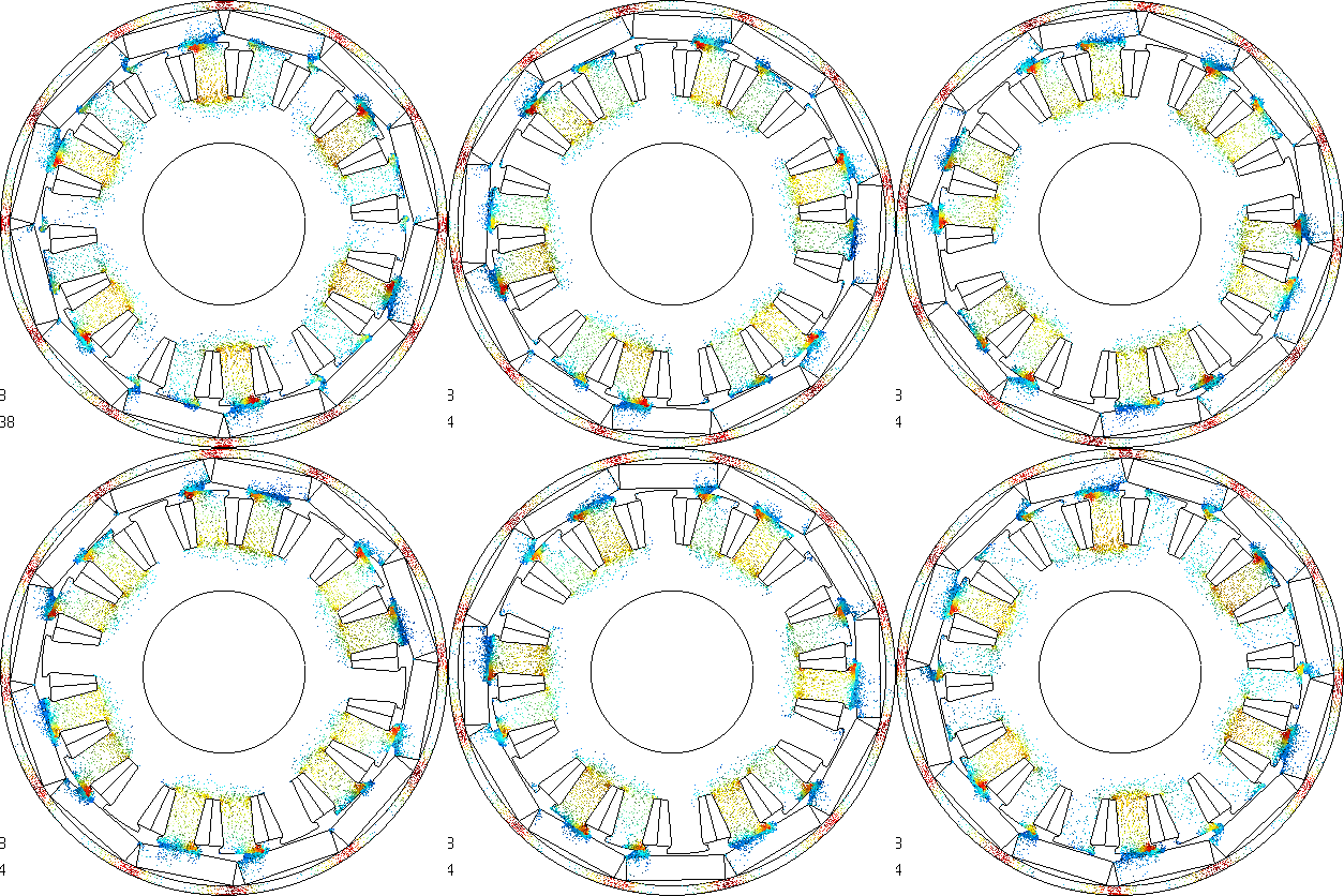
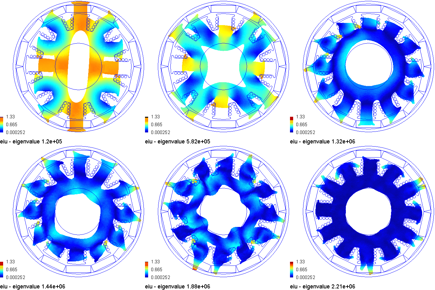
My personal tool rlib is primarily a collection of “Design Automation and Design Optimization” functions. It helps me use the software that solve the following Maxwell’s equations.
$$ \nabla\times\vec{B} = \mu_0 \vec{J} + \mu_0 \epsilon_0 \frac{\partial{\vec{E}}}{\partial t} $$
$$ \nabla\cdot\vec{B} = 0 $$
$$ \nabla \times \vec{E} = - \frac{\partial{\vec{B}}}{\partial t} $$
$$ \nabla\cdot\vec{E} = \frac{\rho}{\epsilon_0} $$


Purpose
This tool rlib is a by-product of my efforts to ease the use of electromagnetic design software, both open-source and commercial. This effort is primarily related to design automation and design optimization.
Geometry Construction features
Apart from being able to create standard geometries for the Inner/Outer Rotor Surface Mounted Permanent Magnet motors, Inner Rotor Interior Permanent Magnet Motors and Inner Rotor Synchronous Reluctance Motors, rlib can also create few geometrical and procedural variations. The following are some of the features of rlib.
- Functional and robust
- The FEMM based workflow has created and solved over 1 million valid models so far
- Same geometry checks are used for Flux, Gmsh and Elmer model creation
- Most of the errors in the code are eliminated, with a very few known bugs
- The FEMM based workflow has created and solved over 1 million valid models so far
- Validated and calibrated models
- BLDC topologies have been prototyped and tested on the dynamometer and predicted characteristics such as the Peak Torque, Max Speed, corner speed, kt and others have been validated
- Phase resistance values are calibrated from the prototyped values
- Completely parametric
- Every geometrical parameter can be changed from the command-line or the script file
- Many solver settings and configurations can be controlled from the script
- Individual wire strands placement
- Circular and rectangular wires can be placed in the slot
- Wire placement algorithm was developed
- supports tilting the rectangular wires to match the tooth wedge angles
- supports placing individual wires in top half and bottom half of the slots for multi-throw winding
- Creating air pockets in the Stator or Rotor BackIron regions
- These air pockets can be created specific to the geometry and be customized
- These pocket entries can be created through the Scilab graphics plot, or manual table entry
- Rectangular magnets
- Instead of the arc magnets for the surface mounted machines, rectangular magnets can be used
- Magnet overhang is supported for rectangular magnets too
- Consequent poles
- Supports for the surface mounted configurations, with arc magnets (any pole arc) and rectangular magnets
- Creating the tooth stem angle
- Not just parallel slots and parallel teeth design, but any angle in between
- Halbach array configuration
- Arc magnets may be configured to two variations of Halbach arrangements
- first arrangement is radial and tangential magnetization
- second arrangement is tangential and inclined ( to radial direction, two halves) magnetization
- Arc magnets may be configured to two variations of Halbach arrangements
- Rotor eccentricity
- Static or dynamic eccentricity can be emulated
- Magnet overhang
- Can specify the magnet overhang of the 3D models in Gmsh and Elmer. Still working on Flux 3D model creation (automatically)
- Customized winding pattern
- Can include non-uniform turn number for individual slots
- Can create and specify the winding pattern through the coil throw parameter
- Can specify non-standard winding pattern by assigning the corresponding string to the variable
- Can support multi-throw winding
- The slot can be split horizontally as opposed to vertical split in the single throw winding for BLDCs.
- Automatic valid geometry creation for any pole/slot combination
- Works for every valid pole-slot combination
- Indicates the winding imbalance for invalid pole-slot combinations
- Inspecting the geometry
- Checks the geometry for any spatial violation
Control Features
- Temperature sensitive simulations
- Temperature is an important parameter that corrects the winding resistance, and the magnet’s BH curve
- Material customization
- The magnetic material, winding material, lamination material can be completely customized
- Control Simulation
- BLDC control logic has been implemented for surface mounted motors by default
- Id-Iq based control is implemented for IPM type by default
- The control may be changed
Simulation FEAtures
- FEMM solution
- Series of magneto static simulations
- Solving the motor in FEMM for complete characterization
- Speed-torque plots
- Torque-Vs-Current-Vs-Rotor Position maps
- Airgap magnetic flux density
- Demagnetizing effects on the magnets
- Stator/Rotor backiron saturation
- Cogging torque
- Back-emf waveforms
- Line/Phase self and mutual inductances
- Radial pull force on the rotor with/without rotor eccentricity
- Characterization happens with parallel operation
- multiple FEMM models are created with different rotational angles
- resulting data is collected by reading the files and appended to the main variables
- saves time drastically
- FEMM optimization
- Gradient descent based and stochastically driven
- Targets global maxima
- Changes every possible geometrical parameter
- Changes winding turn count, parallel strands, and wire diameter
- Matches the set slot fill
- Pass criteria and thresholds
- Top/Bottom limits of chosen parameters
- Every parameter change can be one of normal distribution, uniform distribution, or random selection from a set
- Data visualization during the optimization process
- saves every motor analyzed including the results as .odR files
- saves optimization settings as .osR files
- data files can be read and processed to csv files
- this operation can be paralleled where batches of file are read using multiple Scilab instances
- resulting output file is an amalgamation of individual files
- Gmsh geometry
- Creates 2D and 3D models and unrolls them for simpler loading. A 3D model with about 5 million degrees of freedom (after meshing) can be loaded in less than 1 second.
- 2D models are created from parameterized specifications of the motor, and boundary surfaces defined.
- 3D models are much beyond simple extrusions
- 3D models are extruded, additional 3D features added, surface boundaries added
- Creates 2D and 3D models and unrolls them for simpler loading. A 3D model with about 5 million degrees of freedom (after meshing) can be loaded in less than 1 second.
- Gmsh solution
- Creates .pro file with magnetization profiles, material characteristics and physical group numbers
- At the moment, limited to 2D solutions only
- Elmer geometry
- Creates mesh. files from .msh files
- 2D workflow is stabilized, working on 3D mesh creation through import or extruding 2D mesh.
- Elmer solution
- Creates .sif files with magnetization profiles, material characteristics and physical group numbers
- 2D solution works fine and the data was visualized in ParaView.
- 3D solution and multi-physics solution needs to be tried out.
- Geometry creation for simplified calculations
- each geometry is created with the Stator and the Rotor relative positions at their maximum torque producing values according to the control scheme chosen
- Peak torque detection algorithms
- to identify the realistic rotor position that produces actual peak torque including the geometry variations, reluctance effects and cogging effects
- has control the number of points needed to be sampled on either side of the peak value (of torque vs rotor angle plot) to reduce the number of FEA simulations
- also useful for peak cogging torque estimation
Operational environment
The rlib has been developed and tested in the following environment
- Windows 7 and 10, 64bit versions
- Scilab (v5.5.2), 64 bit version
- FEMM 4.2(x64, Released on Jan 12, 2016 & 25 Feb, 2018)
- Flux (v12.3.1 and v2018), 64 bit versions
- Gmsh (v3.0.6 and v3.0.7), 64 bit versions
- GetDP (v2.11.4), 64 bit version
- Elmer (v8.2), 64 bit version
Present status
I was able to create the following workflow
- Geometry creation
- FEMM {.fem file is created through scifemm interface} - supports IR/OR BLDC and IRIPM
- Gmsh {2D & 3D including boundary conditions}({geo file is creation through Scilab scripts} - supports OR BLDC so far
- Elmer {2D and 3D including boundary conditions}{mesh.__ files are created with elmergrid using the .msh files} - supports OR BLDC so far
- FLUX {2D geometry creation so far.} - supports IR/OR BLDC and IRIPM
- Magnetostatic simulations
- FEMM (built-in solver) - worked on 2D geometry
- Gmsh (with GetDP)(.pro file is created from Scilab scripts) - worked on 2D so far, supports 3D as well
- Elmer (with 2D MagnetoStatic solver)(.sif file is created from Scilab scripts)- worked on 2D so far, supports 3D as well
- FLUX ( built in solver) - worked on 2D so far, supports 3D as well
- Transient Magnetic
- Gmsh (with GetDP) - worked on 2D so far, supports 3D as well
- FLUX ( built in solver) - worked on 2D so far, supports 3D as well
- Optimization routines
- FEMM - Scilab : Scilab controls FEMM actions and model parameters. It also creates new models based on previous simulations to derive parito front and the best possible solution.
- Routine is based on modified gradient descent algorithm that searches for global maximum
- Can work with value-constrained and step-constrained multi-variate environment
- Can also do sensitivity analysis
- Works with the set thresholds on chosen variables
- FEMM - Scilab : Scilab controls FEMM actions and model parameters. It also creates new models based on previous simulations to derive parito front and the best possible solution.
- Motor characterization
- FEMM - Scilab : Can characterize the motor for the following
- Speed-Torque curves
- Torque-Vs-Theta plot
- Cogging torque-Vs-Theta plot
- Torque-Vs-Current-Vs-Theta plot
- Inductance-Vs-Current plot
- Induced voltages Vs. Theta plots
- Radial pull force with/without rotor offset
- FLUX : Can characterize the motor for the following
- Speed-Torque curves
- Torque-Vs-Theta plot
- Cogging torque-Vs-Theta plot
- Torque-Vs-Current-Vs-Theta plot
- Airgap Flux Density and the frequency spectrum
- Induced voltages Vs. Theta plots
- FEMM - Scilab : Can characterize the motor for the following
- GUI for editing
- Can edit the motor and optimization variables from GUI - however, better control exists from commandprompt
- Hand-coded scripts
- rlib is composed of common,data and geometry files for all the motor topologies
- common functions file is about 10,000 lines long
- data handling functions file is about 600 lines long
- geometry definition/creation file is
- about 5800 lines long for OR BLDC
- about 2800 lines long for IR IPM
- about 2000 lines long for IR BLDC
- rlib is composed of common,data and geometry files for all the motor topologies